
VRC V5 2024-2025 High Stakes Robot
June 2024 - Jan 2025 Role: Lead of Design, Build, Coding
As the Mechanical Lead of the Team, I played a core role in addressing the challenges of the VRC 2024-2025 High Stakes competition. Below is a detailed elaboration of our team’s workflow across key engineering design phases to meet the competition’s requirements.

Identify the Problem
The VRC High Stakes competition requires robots to score points through specific tasks, and my mechanical design work focused on solving the following core challenges:


Scoring Efficiency
Robots must deposit rings onto wall stakes (alliance stakes: 16.5” off the ground; neutral stakes: 25” off the ground) and mobile goals (mogos) (max 6 rings per goal, with doubled points if placed in positive corners). Our initial designs struggled with slow ring intake and unreliable redirection to either the basket (for wall stakes) or mogos.
Autonomous Performance
Securing the Autonomous Win Point (AWP) and 6-point auton bonus was critical for match wins, but this required precise drivetrain control and consistent subsystem coordination—something our early prototypes lacked.
Size & Durability Constraints
The robot needed to fit within an 18” starting size (24” expansion limit) and weigh under 17.4 lbs (for Robot 1), while withstanding collisions. Our first drivetrain was too bulky, and the mogo clamp failed to grip mogos from all orientations without high air consumption.
Arm Reliability
The arm for wall stakes needed to reach 25” (neutral stakes) with enough torque, but early designs were either too heavy (reducing maneuverability) or lacked stability (causing rings to slip during scoring).
Research
To inform our mechanical designs, I led targeted research on subsystems and competitive best practices:


Drivetrain
I analyzed top teams’ designs, such as Team 334U’s 450 RPM tank drive (3.25” wheels) and Team 2029C’s 360 RPM setup, to compare wheel sizes (2”, 2.75”, 3.25”, 4”) and gear ratios (36:48, 48:60). I used CAD to test spacing for 6×11W motors (to maximize torque) and ensure compatibility with other subsystems.
Intake
I studied Team 18518A’s ring guides, Team 360X’s basket-intake integration, and Team 229V’s dual-function intake. This helped us weigh options:
flex wheels: high grip for ground rings
elastic rollers: lightweight but prone to snapping
hook-with-chain systems: fast redirection with fewer moving parts
Mogo Clamp
I reviewed Team 210Y’s claw and Team 2145Z’s pre-season clamp to fix our grip issues. Through CAD simulations, I tested leverage mechanics to reduce air use—critical for avoiding mid-match pneumatic failures.
Arm
I researched arm types (two-bar, four-bar, DR4B) using data from Team 5225A’s successful DR4B design. My focus was on balancing height reach (min. 25” for neutral stakes) with weight, as a heavy arm would slow the drivetrain.
Sensors
I tested rotation sensors (to replace slow distance sensors for intake positioning) and odometry tracking wheels (for autonomous accuracy), using CAD to map sensor mounting spots that avoided interfering with moving parts.
Brainstorm Possibilities
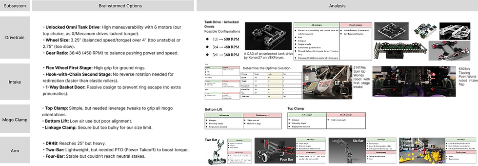
I facilitated brainstorming sessions to evaluate technical options for each subsystem, prioritizing speed, durability, and rule compliance:
.png)
Key decisions:
Drivetrain: Unlocked omni tank drive with 3.25” wheels and 36:48 gear ratio.
Intake: Flex wheel first stage + hook-with-chain second stage (for “instant redirection”).
Mogo Clamp: Optimized top clamp (with lever adjustments to reduce air use).
Arm: DR4B for Robot 1, two-bar with PTO for Robot 2 (to save weight).
Design Process
After brainstorming, we didn’t jump straight to building—instead, I led three critical steps to refine our ideas, ensure compliance, and avoid costly prototype failures:
First, I led the team to filter out ideas that failed to meet our constraints (size, weight, air use, time) or competition rules. This left us with a narrowed list: unlocked omni tank drive, flex wheel + hook-with-chain intake, optimized top clamp, and DR4B/two-bar arms.

-
Drivetrain: We eliminated X-Drive and Mecanum Drive—X-Drive had insufficient torque for pushing mogos, and Mecanum Drive wasted space. We also ruled out 4” wheelsand 2.75” wheels.
-
Intake: We cut elastic rollers because the bands snapped easily during collision tests. Flap intake designs were rejected too—they lacked grip for heavy rings and broke after repeated impacts.
-
Mogo Clamp: The linkage clamp was discarded for being 2” over the 18” starting size. The bottom lift clamp was axed after CAD simulations showed it needed 80+ psi to lift a full mogo.
-
Arm: The four-bar arm was eliminated—it only reached 22” even with maximum extension.
To pick the best final designs, I created a weighted decision matrix for each subsystem, scoring options against priorities like speed, durability, and size. This matrix ensured our choices were data-driven, not just subjective.
-
Drivetrain: We eliminated X-Drive and Mecanum Drive—X-Drive had insufficient torque for pushing mogos, and Mecanum Drive wasted space. We also ruled out 4” wheelsand 2.75” wheels.
-
Intake: We cut elastic rollers because the bands snapped easily during collision tests. Flap intake designs were rejected too—they lacked grip for heavy rings and broke after repeated impacts.
-
Mogo Clamp: The linkage clamp was discarded for being 2” over the 18” starting size. The bottom lift clamp was axed after CAD simulations showed it needed 80+ psi to lift a full mogo.
-
Arm: The four-bar arm was eliminated—it only reached 22” even with maximum extension.

I spent 2–3 weeks refining every subsystem in CAD to avoid fit issues during building. I also checked subsystem compatibility: for example, I moved the intake 1” forward in CAD to prevent the DR4B from blocking ring flow, and adjusted the mogo clamp’s position to keep the robot’s center of gravity balanced.

-
Drivetrain: I modeled the 6-motor layout and tested spacing for 3.25” wheels—adjusting axle positions by 0.5” to ensure gears didn’t scrape the ground. I also added custom lexan braces in CAD to fix spacing from wider gears.
-
Intake: I designed the flex wheel first stage with 5 wheels to cover the robot’s front width. For the hook-with-chain second stage, I mapped the chain path in CAD to ensure hooks stopped at exactly 45° without hitting the intake frame.
-
Mogo Clamp: I adjusted the top clamp’s lever length in CAD—lengthening it by 1” to reduce activation air pressure from 70 psi to 50 psi. I also added lexan funnels to guide mogos into place, fixing alignment issues.
-
Arm: For DR4B, I shortened C-channels in CAD from 12” to 10” to keep the arm under 29”. For the two-bar arm, I modeled the PTO connection to the intake motors—ensuring the gear train didn’t slip when switching between intake and arm modes.
Before building, I led parts preparation to save time.

-
Bill of Materials: I compiled a list of 3D-printed parts and VEX stock parts . We ordered extra flex wheels and pneumatic tubing.
-
Custom Part Cutting: I cut lexan sheets to the exact dimensions from CAD using a laser cutter—this ensured parts fit together without filing or sanding.
-
Pre-Testing Small Components: I tested key small parts first—for example, we ran the hook chain through a mock intake frame to check for jams, and tested the clamp’s piston with 50 psi air to confirm it lifted a 5-lb weight.
Build Prototype
I led the physical prototyping process, using CAD to refine designs before hands-on construction:
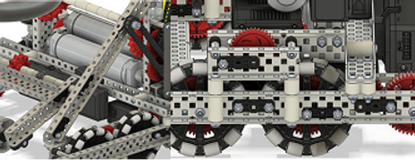
Intake Prototype
-
First Iteration: I built an elastic roller intake, but switched to a hook-with-chain design in June. I relocated the motor to the front, added a rotation sensor for precise hook positioning, and cut lexan ramps to guide rings into the system.
-
Redirection Integration: I mounted a 1-way door on the arm’s basket and adjusted the intake-basket angle via lexan cuts. This let rings move from the ground to the basket “instantly”—no reverse rotation needed, which saved time during matches.
.png)
.png)
Drivetrain Prototype
-
CAD Design : I redesigned our initial 8-wheel drivetrain to 6 wheels, shortening its length from 18” to 17 units. I stacked rear motors vertically to free up front space for the intake, and used CAD to test screw joint placements.
-
Physical Build: I assembled 6×11W motors, 3.25” omni wheels, and 36:48 gears. To fix spacing issues from wider gears, I cut custom lexan braces to hold components in place—this prevented gear slippage during collisions.


Mogo Clamp Prototype
-
Iterations : I first built a bottom-lift clamp (used 80+ psi, too much air). Next, a linkage clamp . Finally, I simplified to a top clamp: I moved pistons lower for better leverage, added a c-channel crossbar for grip, and used lexan to adjust the angle. This reduced activation pressure to 50 psi.


Arm Prototype
-
DR4B: I built a DR4B with 2×5.5W motors, shortened C-channels to keep height under limits (31” → 29”), and repositioned L-channels to avoid blocking the intake.
-
Two-Bar: To save weight, I switched to a two-bar arm. I added a PTO to connect 2×11W motors (boosting torque) and a rotation sensor to track height. I also used lexan bracing to prevent gear skipping.


Test and Evaluate
Drivetrain Testing
-
Friction & Speed: We spun wheels without motors (target: 5+ seconds free spin). The left side had high friction— I adjusted bearing placement and replaced a bent axle, boosting RPM from 551 to 594 (near max 600 RPM).
-
Maneuverability: We pushed the drivetrain to test straight movement. I added idle gears between front wheels to distribute weight, preventing the robot from sinking into foam tiles.

Intake Testing
-
Speed & Accuracy: We tested 10-ring cycles. At 100% power, cycles took 0.65s but overheated motors— I adjusted to 90% power and added guiding rails, cutting jams from 3/30 rings to 1/30.
-
Redirection: Early tests failed 30% of the time. I split the door into two side-opening flaps, boosting success to 90%.


Mogo Clamp Testing

-
Grip & Air Use: We tested gripping mogos from edges/corners (target: <70 psi). My optimized top clamp worked at 50 psi (empty) and 70 psi (full)— a big improvement over the 80+ psi of early designs.
-
Driver Usability: Our driver (Anson) practiced gripping mogos. I added lexan funnels to auto-center mogos, cutting alignment time by 50%.
Arm Testing
-
Height & Torque: The DR4B initially reached 31” (too tall)— I shortened C-channels to 29” and added aluminum bracing, letting it hold 2 rings (~150g) without bending.
-
Two-Bar Optimization: Gear skipping was an issue— I added a lexan sheet to secure gears, eliminating slips and reducing motor temp from 43°C to 40°C (sustained use).


Conclusion
By leading the team through the engineering design process—identifying problems, researching solutions, brainstorming options, building prototypes, and testing rigorously—we developed a robot that met High Stakes’ challenges. Key outcomes included:
-
A fast, durable drivetrain (450 RPM, 3.25” wheels) for maneuverability.
-
An “instant redirect” intake (flex wheel + hook chain) with 90% accuracy.
-
A low-air mogo clamp (50 psi activation) that grips from all orientations.
-
A lightweight two-bar arm (Robot 2) that reaches 25” stakes reliably.
These subsystems helped our team compete at the 2025 VEX Robotics World Championship and win awards like the Design Award at the Caution Tape Halloween Qualifier—proving our approach to solving the competition’s challenges was effective.
